Overview
There are two fundamental types of connection tools used by Blueprint:
- Event Connection Tool
- Reference Connection Tool
The Event Connection tool is used to create real connections that carry events between the nodal objects. The Reference Connection tool is used to create references to object connection points. These references can take the form of:
- Definition Pins (to reference objects across circuit boundaries)
- Label Publications (to reference objects in the same circuit without a connection line)
- Conduit Publications (to reference objects in the same circuit using a bus-style connection line)
In this case, the reference source does not make a real connection to the reference target, but exposes an alias of the reference target to which a real connection can be made using the Event Connection tool. For more information see Connections
Event & reference connections can be made between objects within a circuit definition or a container definition. In addition, the Event Connection tool can be used within prototypes to create prototype event connections.
Connecting Objects Within a Definition
To connect two objects within a definition you must perform the following steps:
- Select the type of connection required (Event or Reference) from the toolbox in the Connections category
- Select a valid start point
- Select a valid end point
- Adjust the connection end point placement (optional)
- Adjust the connection line routing (optional)
- Modify connection properties (optional)
Select a Valid Start and End Point
Event connections and Reference connections are created in the same way, but with different restrictions on what are valid end points.
Event Connections
Event connections must always be made from a consuming object to a providing object. Objects can be providers or consumers or both and in the case where they are providing and consuming it is important to connect to the correct part of the object in order to make the required connection.
In this case, the main body of the object will represent either the providing or consuming part of the object and it will have a separate face that represents the consuming or providing part respectively. The main body of the object always accepts just one connection and the face allows multiple connections. Therefore a collector, which consumes multiple events and provides a single event has a consuming face and a providing body, whereas a distributor, which consumes a single event and provides multiple events has a providing face and a consuming body.
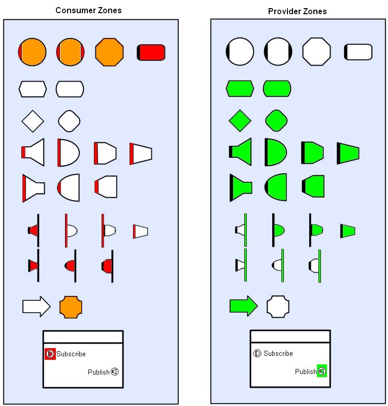
Reference Connections
Reference connections must always be made from a reference source to a reference target (for more information see Connections)
Start Point
Method or Thread
End Point
Device
Start Point
Provider Definition Pin or Consumer Definition Pin
End Point
Event Providing Object or Event Consuming Object
Reference connections are also used with conduits (see Connecting to Conduits below)
Feedback on Validity of Connection End Points
When selecting a start point, Blueprint will automatically track the cursor
and change the pointer type from ![]() (invalid start point) to
(invalid start point) to  (valid start point) when it hovers
over each object.
During the drag to the end point the cursor will change from
![]() (invalid end point) to
(invalid end point) to  (valid end point) as it is dragged
over each object. In general connections must be made from a consumer face
to a provider face, or from a circuit pin to an object.
Adjusting the Connection End-Point Placement
When a connection is first made, Visual Studio will snap to points based on
a regular spacing and not always to the face you intended (correct
provider/consumer face but may be on the other side etc.). If this is the case
the end points can be moved immediately (do not select anything), move the
cursor over the end point (cursor changes to  ) select the end point and drag it to the correct
location. An end point can also be moved to a new location on the face for
alignment/visual effect in the same way.
Once a line has been deselected, moving an end point (to another point on
the face, or to another (valid) face) is slightly different. Again
do not select the line! just hover the cursor (with no selections made) over
the end point. When the cursor changes to  the point can be selected and moved. If the cursor
changes to
  then
the line is being selected not the end point. If the end point is moved to an
invalid face it will snap to the nearest point on a valid face. End
points cannot be moved when the line is selected.
In most cases the location of a connection on a face is purely visual. However, when connections are made to Ordered Collectors the visual ordering becomes the actual ordering.
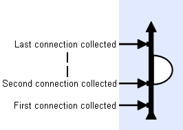
Adjusting the Connection Line-Routing
Once a line has been created and its route auto-calculated, it can easily be re-routed for visual effect. Simply select the line
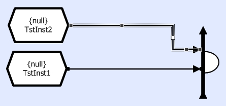
and drag the white or black points (not the end points) to the new locations. Alternatively a route can be automatically re-calculated by selecting 'Re-Route' from the Pop-Up menu.
Modifying Connection Properties
When a connection is selected the Properties window shows the attributes for that connection. Each connection has a different set of attributes depending on the objects that it connects (see the general section on Connections and the sections on specific connections).
The figure below show a typical Properties window
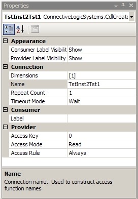
A number of attribute categories can be shown
- Appearance
- Connection
- Consumer
- Provider
The items shown under each category are dependent on the connected objects and the connection faces.
The most common property that requires changing is Access Mode. This determines the direction of the arrow on the diagram to show whether the consumer is requesting Read, Write, Update or Notify Updated access.
Connections To Circuit Instance/Reference Pins
Connecting objects to sub-circuits or sub-circuits to sub-circuits (whether Local or Reference) follows the same rules and procedures as object-object connections (i.e. connect from a consumer object/pin to a provider object/pin).
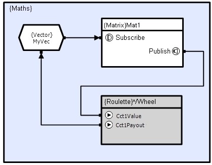
Using T-Bars
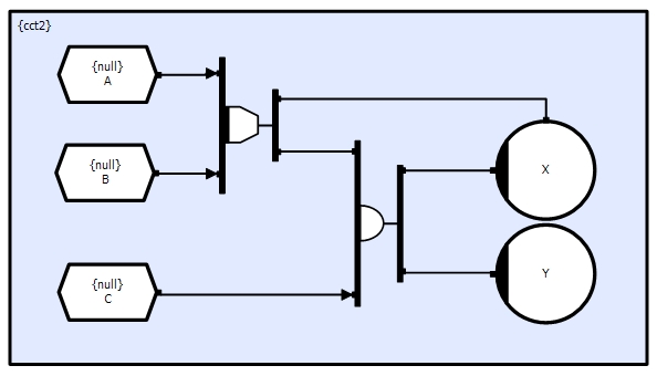
When multiple connections are made to an object that only has one connection point, a T-bar will be automatically generated (objects that have multiple connection points/faces will not generate a T-bar even when connections are made to the same point). When the number of connections is reduced back down to one, the T-bar is automatically removed.
Once created, T-bars can be moved/extended like any other object, as can the connection points to the T-bar.
Using Labels
Sometimes it is necessary to make many connections that would lead to crossed lines and therefore make the circuitry difficult to read. In this case, Blueprint provides another means of connecting, referred to as labels. Any object can have named publication labels attached to its faces. Other objects can then make connections to these labels by referencing the publication's name. This allows many connections to be made to the same point from all over the circuit definition, without requiring connection lines to be drawn between them.
The following example shows a transient store, Store, with a publication label providing a named connection point to its providing face. The two methods, MethodA and MethodB, are connected to the store through the publication label (small circle with gray background). The actual connection is drawn from the method trigger face to a reference label (small circle with white background) that has the same name as the publication label.

Creating a publication label involves dragging a reference connection from the circuit background to the object being referenced as follows:

Creating a reference label involves dragging an event connection from the consuming object to the providing publication label as follows:

Connection Signatures
When connecting arrays of objects, Blueprint will automatically generate a wiring matrix depending on the array dimensions of the two objects. This matrix matches any common dimensions and makes a direct link between these elements. For, any non-matching dimensions the matrix makes a connection to every element (see Basic Connection Signatures examples).
In most cases this is what is required. However, sometimes it is necessary to manually define the matrix. This can be done using the Connection Editor, by selecting the Edit Mapping -> Connection Signature menu item from the connections right-click context menu.