Overview
Circuit definitions may contain any of the following objects:
- Circuit Instances
- Circuit References
- Primitive objects (e.g distributors, stores etc.)
- Definition Pins
- Labels
- Comments
Container definitions may only contain:
- Circuit Instances
- Comments
Colony definitions may only contain:
- Processes
Adding Primitive Objects to a Circuit Definition
To create a new primitive object within a circuit definition you must perform the following steps:
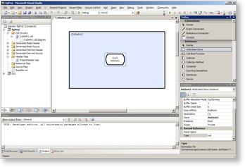
- Open a previously created circuit definition file from the solution explorer (see Creating a Circuit Definition).
Click to enlarge
- Drag objects from the Toolbox (Instances) on to the circuit definition (the tool object selection is not sticky, ie. when an object is dropped the system reverts back to the Pointer tool). Whilst dragging, the cursor will change to
when a drop point is valid or
if not valid.
- Once placed on the circuit, objects can be moved by selecting a single object or a group of objects and dragging with the mouse or pressing the cursor keys (see Manipulating Objects below). Many objects can also be rotated, by using <Ctrl>+Cursor Keys.
Adding Circuit Instances to a Circuit or Container Definition
To create a new Blueprint definition you must perform the following steps:
- Locate the definition that you want to instantiate in the Custom Definitions tool window (see Creating a Circuit Definition).
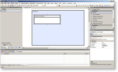
- Left-click-drag the definition from the Custom Definitions tool window to your circuit definition object and drop it. An instance of the definition that you dragged will appear within your circuit definition:
Click to enlarge
- Alternatively, by right-click-dragging the definition on to the circuit definition, a circuit reference is created (see Circuits for more information about the difference between an instance and a reference).
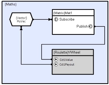
If a circuit definition defines connection pins then instances of that definition provide corresponding connection points. These pins provide a means of passing events to and from the circuit and connections can be made to/from these connection points in just the same way as connecting to a primitive object of the same underlying type. However, there is an additional constraint that the connected objects must conform to the pin's prototype. Instance/reference pins can be moved up and down by dragging them and this allows you to improve the layout and avoid crossed lines. The example below shows a circuit definition containing a connected circuit instance and reference:
Manipulating Objects
Selection/Deselection
There are several ways to select entities within the diagram:
- Single click within the object's catchment area
- Select multiple objects by dragging a box around them (items must be completely enclosed)
- Select multiple objects by holding <Ctrl> and clicking each object within their catchment area
Objects can be deselected in two ways:
- Hold <Ctrl> and click on the object within its catchment area to deselect that single object
- Do not hold <Ctrl> and click outside of the object's catchment area (this will deselect all objects whose catchment area does not enclose the pointer)
Definitions exhibit special selection behavior in order to allow box selection within their boundary. This means that they can only be selected by clicking close to their perimeter.
Deletion
Objects can be deleted, by either:
- Selecting the Delete option from the Pop-Up menu; or
- By pressing the Delete key
Any connections that are attached to the object will be deleted as well.
Extendable Faces
Some objects (small variants) have connection faces that can be extended (Distributor, Collector, Multiplexer, Splitter, De-multiplexer and T-bar).
To extend a face, select the object face, this will display its drag handles.
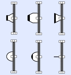
These handles can then be dragged to change the length (any thickness drags are ignored). The length can also be changed via the cursor keys (see Display Properties below).
Display Properties
Many objects have a number of display properties that can be changed. This can be done by:
- Selecting the appropriate object then changing the property in the Properties window;
- Dragging with the Mouse; or
- Via a combination of the <Shift>/<Ctrl> and <Up>/<Down>/<Left>/<Right> Cursor Keys listed below
This section lists these display properties and how to modify them:
Object Size
An objects size can be toggled between
-
Large
-
Small
Selected in the Properties window.
Object Position
The position of an object can be changed by
Move Up/Down
<Up>/<Down>
Move Left/Right
<Left>/<Right>
Object Rotation
The orientation of an object can be changed by (Vertical/Horizontal or Rotation depends on the object selected)
Vertical/Horizontal
<Ctrl> + <Left>/<Right>
Rotated Left/Right
<Ctrl> + <Left>/<Right>
Object Cut Copy PasteCircuit Objects can be copied by using the VisualStudio Cut/Copy/Paste buttons or
Cut
<Ctrl> + x
Copy
<Ctrl> + c
Paste
<Ctrl> + v
Circuit Resize
Circuit Objects can be resized by
Resize Right Side
<Shift> + <Left>/<Right>
Resize Bottom
<Shift> + <Up>/<Down>
Display Position/Size
Display pages can be shifted or zoomed by (no objects selected)
Move up/down
Mouse Scroll Wheel / <Up>/<Down>
Move left/right
<Shift> + Mouse Scroll Wheel / <Left>/<Right>
Zoom In/Out
<Ctrl> + Mouse Scroll Wheel
NB. Only vertical Mouse Scroll Wheel actions are enabled
Viewing and Modifying Attributes
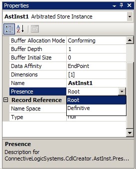
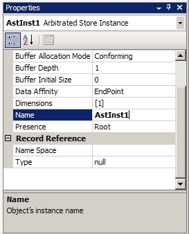
When an object dropped on the page or is selected its attributes are shown in the Properties window (see the appropriate Object sections for a description of the attributes). The attributes for each object can be edited by selecting the appropriate field. Some attributes have a predefined set of options, others have a free input and some a combination of both (see the appropriate Object attributes section for valid inputs, Nodal Objects).
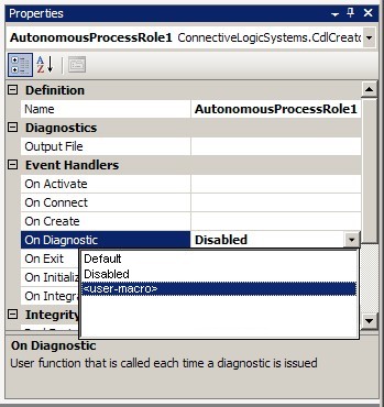
Pre-defined options
|
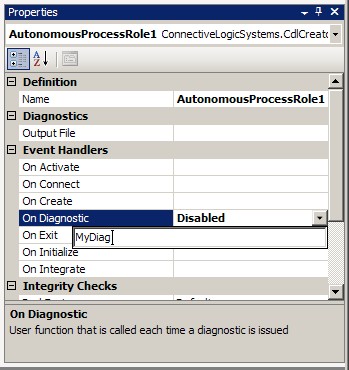
Free Input
|
Pre-defined+Free Input
|
All objects are given a default instance name that is formed from the object type and a number to make it unique. Renaming objects to have meaningful names improves code readability and aids debugging and is highly recommended. This is especially true for Circuits, Methods, Threads, Call-back functions, Stores and Semaphores.
Objects shown using the small variant graphic, do not show the name or dimension (although a [] is shown to indicate it has a dimension).
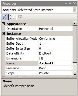
When a field is modified away from the default value it is shown in bold as a reminder. Some attributes (such as Connection Signature) are linked and will be automatically updated if other attributes are changed. However, attributes that have been modified will not be updated.
Values shown in Grey are read-only and cannot be changed, they are shown for consistency.
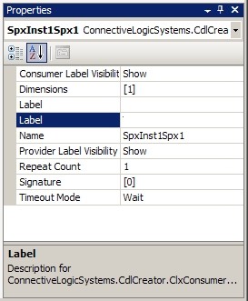
The Properties window shows all of the attributes relevant to the selected object. Like the toolbox, MS Visual Studio allows this window to hide the categories headers and/or list the attributes alphabetically. However, Alphabetical listing is not recommended. The attributes/tools are grouped into associated categories to aid the design process. Without the categories, the names of the attributes can become unclear or ambiguous.
Categorized
|
Alphabetical - Two Label Attributes- which is which?
|
Notes
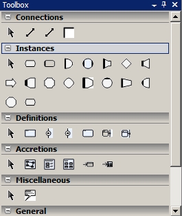
- When adding objects to a circuit it is helpful to have the toolbox organized with the Connection catagory at the top, followed by the Instances category.
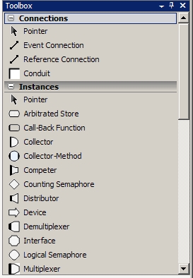
- The exact layout of the toolbox may vary from the picture above. It can be customized by moving tool groups up or down (right click on category item - select Move Up/Move Down) or by removing the text (unselect List View). Hiding textual descriptions is not recommended for inexperienced users:
