Back to Basic GUI Modifications
Creating Circuitry
The Blueprint Project Template generated a complete project structure with a basic accretion, container and main circuit.
Select MyCircuit.cdl from the Solution Explorer file tree.
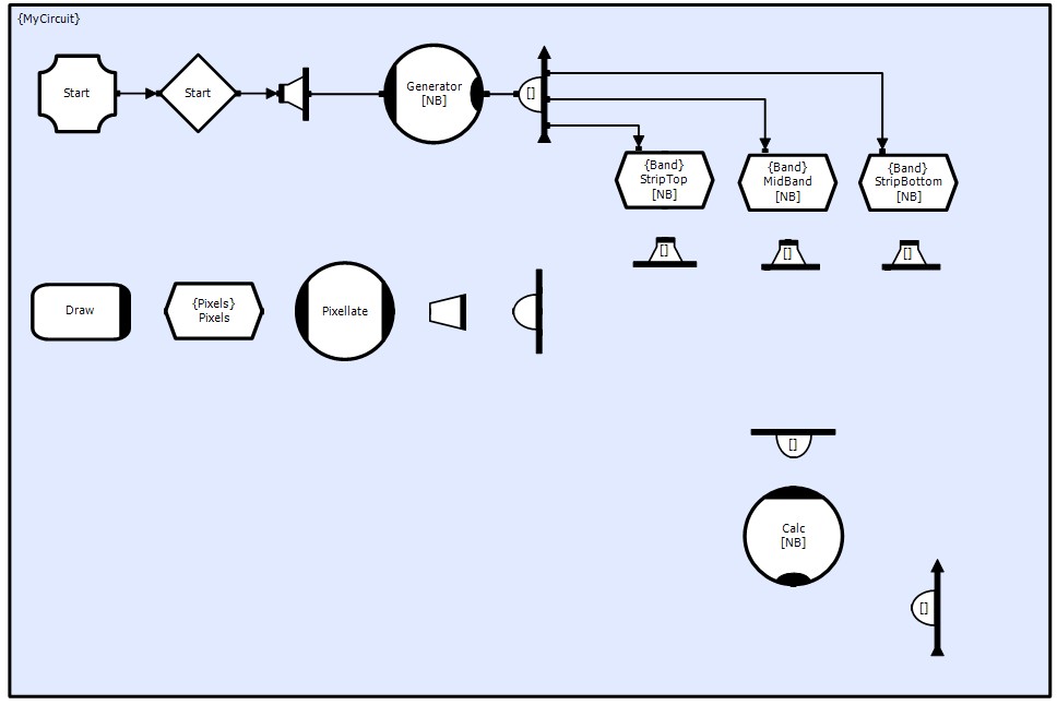
Create the following circuit Objects. The properties of each Object; Name, Dimension, Data Type and Ordering can be set using the Object Properties Window for the selected Object. Whilst its orientation can be controlled by the <Ctrl>+cursor keys.
Notes:
For Generate and Calc, use Collector Methods from the toolbox not the ordinary Methods. You can't change their type once placed.
In general the names given to the collectors and distributers is not important. However, to aid the explanations below and to ensure that the access function names provided in the example code match the correct objects, you need to use the names shown.
All shapes are initially shown large to show names, dimensions and orientation. In later screen shots many symbols will be shown small, hiding some names and dimensions.
The chain Start Interface (Ifce), Start Semaphore (Csm), Start Distributor (Dbx) and Generator Method (Mthd) will be used to initialize and start the Wave Generator processing. An array of Methods is used to parallelize the initialization of the data stores.
The set of TST's StripTop, MidBand and StripBottom hold the current parameters for each cell. They will be updated by the Mthd Calc.
The chain Pix Collector (Clx), Pix Reducer (Rdx), Pixellate Mthd, Pixels TST and Draw Callback (Cbf) will collect all cell results and generate a pixmap for display on the screen. (This chain could be parallelized to display each band separately, however some care would be required to ensure that the same time frame was being displayed at the same time by each Draw. By collecting the cells first ensures that this is not a problem).
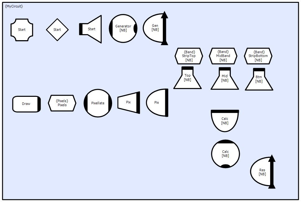
Mthds Calc and Generator are Sequential Collector Mthds, thus they have a hidden ordered collector. This ensures that they do not compete for write access to the 3 data stores. Similarly the Clxs Gen and Res are ordered to collect the three stores in the same order.
Mthd Pixellate is a standard Random Collector Mthd, as there is no problems over competed access. Similarly for Clxs Pix and Calc.
Rdx Pix will be set to throw away many events so that we can drive the processing chain faster than the graphics. Once running the processing will run as fast as it can, we dont want this to be held back by the graphics. This is done by setting the Object's property Period to 'REDUCTION'. The application could be enhanced to dynamically set the reduction rate (this is left as an exercise to the reader).
The stores StripTop, StripBottom and MidBand will use the same data type 'Band' but with different Row/Column sizes. These data structures, along with Pixels will be defined later.
TST buffer depths and Dbx reentrancies should be set to allow Mthds Calc and Pixellate to be operating in different sets of data, ensuring that the processors are kept busy at all times for optimal efficiency. In this example the Buffer Depth of the Strip/Band TST must be at least 2 as Mthd Calc needs to open the stores for both read and write.
TST buffer depth:
Pixels => 2
StripTop, MidBand, StripBottom => DEPTH
Dbx reentrancies:
Top, Mid, Btm => DEPTH
The constant values 'REDUCTION', 'NB', 'DEPTH' can be defined in the project header file by opening the file from the Solution Explorer Window and adding the following code
FDTD/Header Files/ProjectHeader.hpp
...
// TODO: Reference any additional headers or defines you need
#define GRID_SIZE 1024
#define REDUCTION (5*ClpNumProcessors())
#define DEPTH 4
#define NB ClpNumProcessors()
#endif
The function ClpNumProcessors() is a CLIP system service function that returns the number of cores available on the processor. Thus we have set the number of bands to be dependent on the number of available processors, we also reduce the graphics frame rate to maintain about 5-10 frames per sec.
Connections (Cxn)
Blueprint automatically generates connection names dependent on the connection Objects and a counter (there could be more than 1 connection). This auto-generated name is not normally an issue. However to ensure agreement between the names and the example code, it is necessary make the circuit connections in the following steps.
If an object make multiple connections to another object, then renaming the Cxns to more meaningful names (Eg. MyReadCxn, MyWriteCxn etc.) helps identify which is which.
Cxn routing and attachment points can be moved for visual effect, as long as the connection faces are correct and the ordering of connections to Ordered Clxs is correct (the face arrow indicates the order).
The directions of the arrows indicate Read or Write and can be set in the Cxn Properties Window.
First set of connections (all Event Connections)
Second set of connections (all Event Connections)
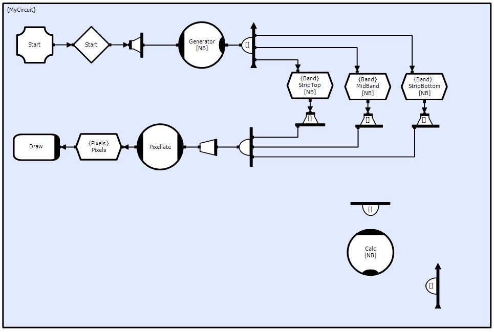
Third set of connections (all Event Connections)
The crossing line loops are automatically added by Blueprint.
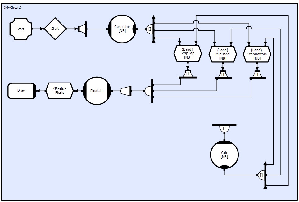
Forth set of connections (all Event Connections)
These last connections are more interesting. The connections to the two Strip TST form the heart of the cross band connectivity.
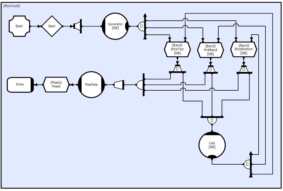
To make the required connection structure each Clx needs to connect to the 'top strip' of the previous band and the 'bottom strip' of the next band. This can be done configuring the connections using the Connection Dialog.
Select the Cxn to StripTop, click the Right Mouse button to pop-up the options menu. Select Edit mapping->Connection Signature...
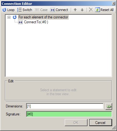
The dialog shows the default connection signature [#0], with each element of the Clx connecting to its appropriate element of the Dbx.
The code generated from this signature is (or it would be if C++ allowed #0 as a variable name).
for ( int #0 = 0; #0 < NB; ++#0 )
{
CalcClx[#0].ConnectTo( TopDbx[#0] );
}
What we need is an additional connection of the form
CalcClx[#0].ConnectTo( TopDbx[#0-1] );
However we only want to make this connection when #0 >= 1 (similarly our connections to BtmDbx will be to [#0+1] for #0 <= NB-2 array elements are numbered 0:n-1)
Thus we need to caveat the connection call
for ( int #0 = 0; #0 < NB; ++#0 )
{
CalcClx[#0].ConnectTo( TopDbx[#0] );
if ( #0 > 0 )
CalcClx[#0].ConnectTo( TopDbx[#0-1] );
}
We can do this in the Connection Dialog by adding a Switch on #0, a Case Minimum (>=) 1 (no Maximum) and a new connection to element #0-1
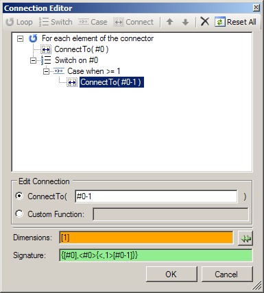
The Signature window is highlighted in green showing that the signature is syntactically valid, but the Dimension window has changed to orange. Due to the Switch Blueprint has identified that the number of connections per element is different, and hence doesn't know what dimensionality to use. So we need to change this to [2], to ensure that the CDL translator generates the access functions for 2 connection elements (don't confuse this with object elements).
For the Btm Dbx connection the setup is similar. However, we cannot use NB-2 in the Case Maximum (<=) specifier (no Minimum), we need to use NB_2 and define NB_2 as NB-2 in the project header file
ProjectHeader.hpp
...
// TODO: Reference any additional headers or defines you need
...
#define NB ClpNumProcessors()
#define NB_2 (NB-2)
#endif
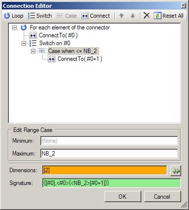
Again we have changed the Dimensions to [2].
