A Finite Difference Time Domain (FDTD) Solver
The classic FDTD calculation, uses a 2-d (or 3-d) grid of cells to calculate a time-varying solution to a mathematical problem across a region. Where the result for each cell is based on the results from the cell and its neighbors at the previous time-frame. Eg. fluid flow, sound waves, radar etc.

The data held for each cell (at each time frame) is usually small (ie, Pressure, Speed, etc) and the processing is also fairly simple. But the number of cells is very large (often in the order of 100s of millions). Although we can build CDL circuitry based on an array of methods (1 per cell), the granularity of the problem will usually result in a poor scaling across a network and poor memory bandwidth across a multi-core processor (see Performance Issues - Memory/Cache).

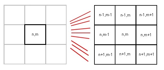
To optimize the solution we could divide the grid into rows rather than cells and get each method to process a row of data. However, this would still result in every row being sent three times (once to the cell in question and twice to its neighbors). To reduce the amount of duplicate data transfers, we need to divide the grid into bands, where only the edge strips of each band needs to be re-sent.

The CDL solution will therefore require 3 arrays of data stores left/top strip, centre band and right/bottom strip. Each method will collect data from 5 stores
- Band X-1 - right/bottom strip
- Band X - left/top strip
- Band X - centre band
- Band X - right/bottom strip
- Band X+1 left/top strip
(apart from the ends which are special cases, which we will deal with in the code).
NB. Although the direction (left to right or top to bottom) of these bands/strips has no processing/logical significance, it has a significant graphics display overhead and so the solution below will process data in horizontal bands.

 Click to enlarge
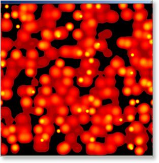
FDTD Rain Generator
The Rain Generator randomly initiates raindrops across the grid and calculates the disturbances out from these points, including all of the resulting interference patterns.
Notes
The sections below describe the complete step-by-step development of the FDTD Rain Generator. When generating this topic we have assumed that the reader has at least read the basic sections of this help documentation, and so the reasons behind every step are not always explained. If at any time the reader is unsure as to why certain steps are being taken, then they should re-read the relevant sections of the documentation.
The code for the processing and graphics functions are beyond the scope of this example, but are provided as code that can be included in your MS VisualStudio project.
Syntax:
Red text : is user entered/modified text
Orange text : is user selected options
Green text : is Dialog/menu field names etc
Black text : is auto-generated by either the CDL translator or the MFC code generator or code previously entered
Magenta text : optional code, either enter ALL or NON of the optional code
... : block of code omitted for brevity
Entering Callback Function Code
The Finite Difference Time Domain solution is available as a MSVisual Studio 2005 solution package from the Connective Logic Web site.
Further Enhancements
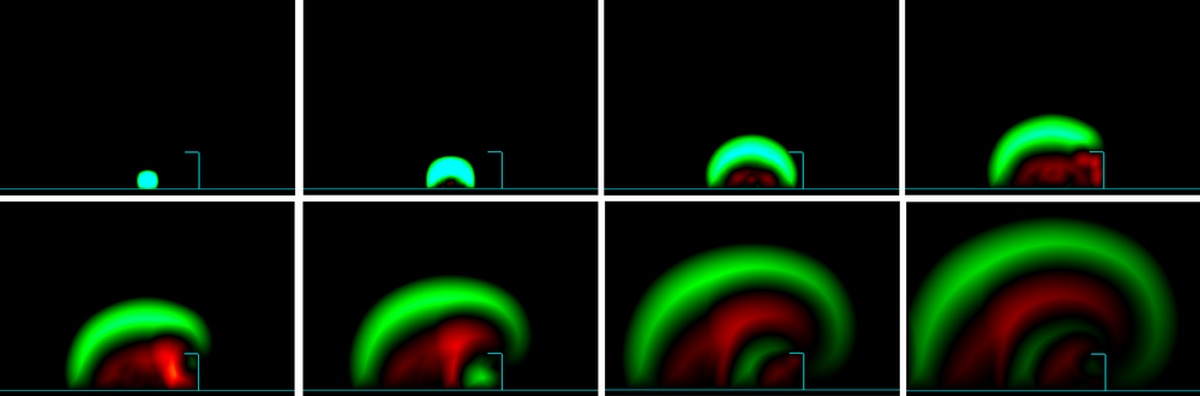
By tweaking the basic maths function F() used in the Calc Mthd (and adding a few extra parameters to the Band data class) the Rain Generator FDTD program can be transformed into any FDTD application. The illustration below shows a series screenshots from an actual application based on the FDTD program.
"Visualization of Pressure Wave Reflection and Diffraction using the Finite Difference Time Domain Method"